Creating BIG-IP DNS Sync Group
The following is adapted from the official F5 documentation:
First start by launching Google Chrome.

In Chrome you should see links to BIG-IP 1 and 2.

Login to BIG-IP 1 username: admin, password: admin
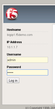
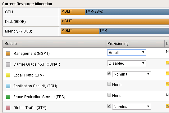
Take a look at the current config. You should see BIG-IP DNS is provisioned.
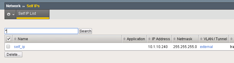
There is an existing self IP.
Configuring BIG-IP DNS
The following will go through the basic steps of setting up BIG-IP DNS.
Enabling DNS Sync
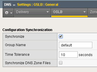
First go to DNS -> Settings -> GSLB -> General
Find the “Synchronize” checkbox and click on it.
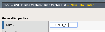
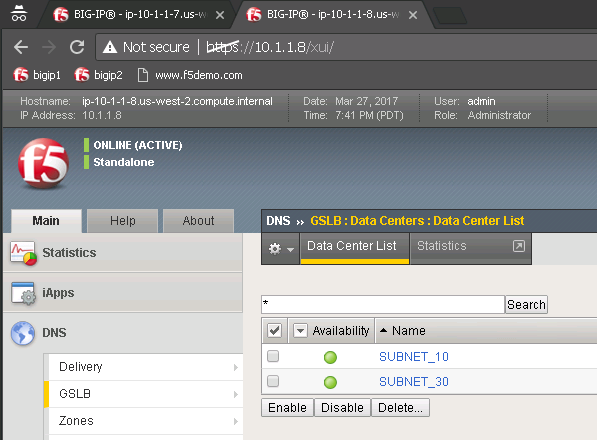
Add Data Center
Next go back to DNS -> GSLB -> Data Centers
Create a Data Center (DC) named SUBNET_10 and SUBNET_30.
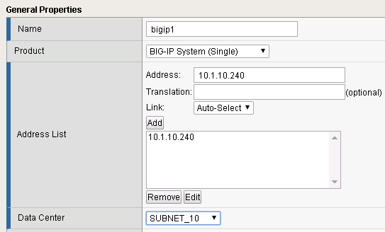
Add Server
Next go to DNS->GSLB->Servers
Create a server bigip1 associated with SUBNET_10 and bigip2 associated with SUBNET_30.
| Name | Address | Data Center |
|---|---|---|
| bigip1 | 10.1.10.240 | SUBNET_10 |
| bigip2 | 10.1.30.240 | SUBNET_30 |
Syncing BIG-IP DNS
At this point BIG-IP 1 has the desired BIG-IP DNS configuration, but it needs to be synced with BIG-IP 2.
From the Desktop launch “Putty”.

Find the BIG-IP 2 login.
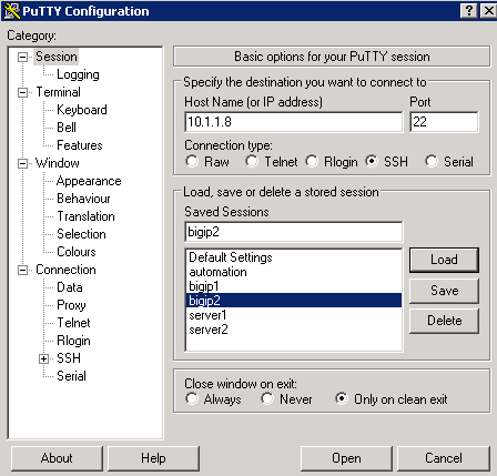
Login. username: admin, password: admin
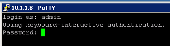
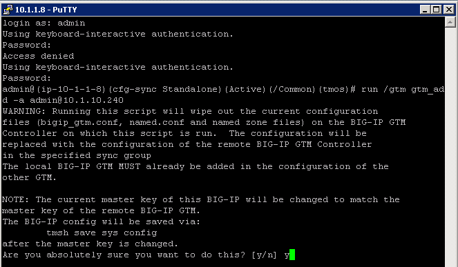
Run the command:
run /gtm gtm_add -a admin@10.1.10.240
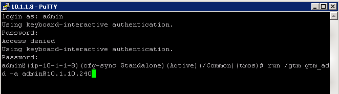
When prompted confirm/enter password.
In Chrome login to BIG-IP 2 and you should see that it is now synced.
You should have a pair of BIG-IP devices that are in a DNS Sync Group. The next lab will go through the process of scripting these actions.
You are now ready to start the next Lab: F5 Python SDK
Optional Exercises
The following next lab, F5 Python SDK, will perform all of the following sections via an automation script. You can choose to perform all of these tasks to understand what the automation will be performing, but at the end of this lab you will delete the work that you have done.
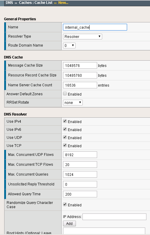
DNS Cache
In the Demo environment we will use BIG-IP DNS as a DNS resolver. Create a DNS cache named “dns_cache”. This needs to be done separately on each BIG-IP device.
Under DNS -> Caches -> Cache List: Create a DNS cache profile “internal_cache” and accept default values.
DNS Profiles
Two DNS profiles are required. One for providing a resolving DNS server and one for external DNS requests (bad idea to have an open resolver on the internet). Now create them on both BIG-IP’s.
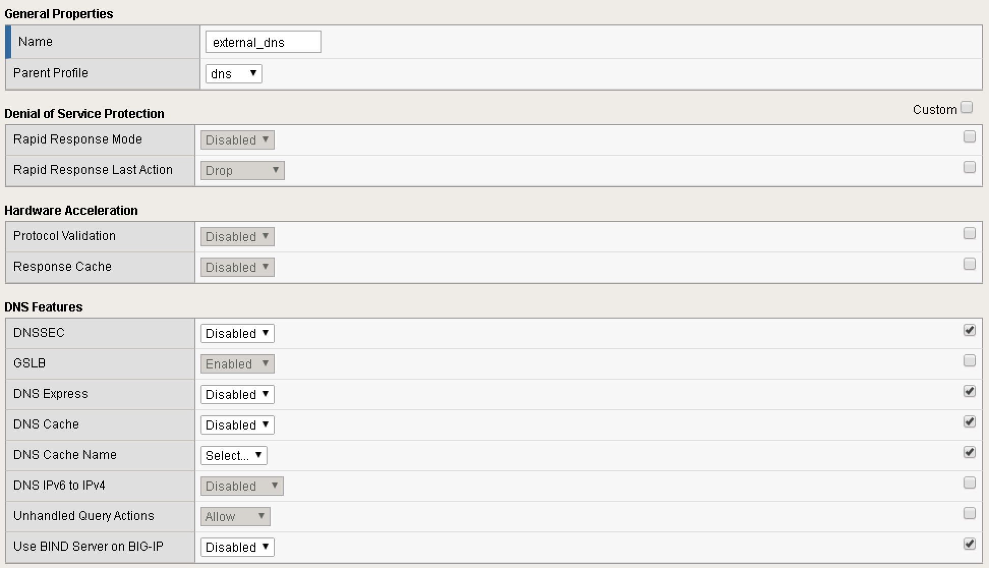
External DNS Profile
Under DNS -> Delivery -> Profiles -> DNS: Create a profile named “external_dns” that only provides GSLB and disables fallback to BIND.
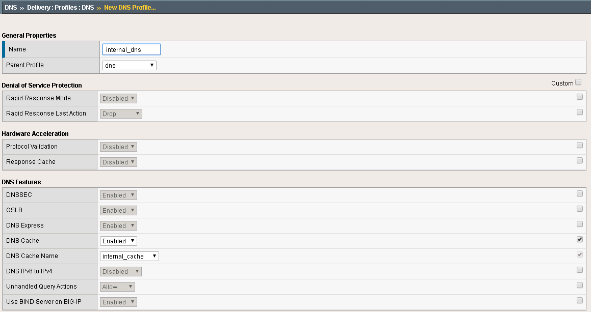
Internal DNS Profile
Under DNS -> Delivery -> Profiles -> DNS: Create a profile named “internal_dns” that enables a DNS cache for resolving names.
DNS Listeners
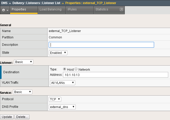
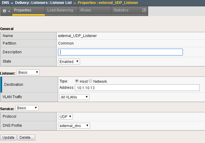
For external DNS we have two listeners for each BIG-IP. One TCP and one UDP. First create on both BIG-IP’s the external Listeners for TCP and UDP. Apply the external_dns profile to each. Use these IP addresses:
| Name | Address | Port |
|---|---|---|
| bigip1 | 10.1.10.13 | 53 |
| bigip2 | 10.1.30.13 | 53 |
External DNS Listener
DNS -> Delivery -> Listeners Here the external TCP listener
Here the external UDP listener
Next go to LTM Virtual server menu. The external listeners will apper as virtual servers.
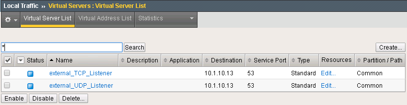
Internal DNS Listener
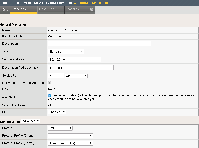
Next create on each BIG-IP internal listeners via the LTM menu. The listener is a virtual server. Specify following source address range on each internal listener: 10.1.0.0/16 and apply the “internal_dns” DNS profile. Keep all other settings as default. Use these IP addresses:
| Name | Address | Port |
|---|---|---|
| bigip1 | 10.1.10.13 | 53 |
| bigip2 | 10.1.30.13 | 53 |
Create listeners for TCP and UDP Here is an example of the internal TCP Listener:
LTM Configuration
Now we have to configure the LTM section of both BIG-IP’s. Since both BIG-IP’s are standalone the configuration steps has to be applied to both BIG-IP’s.
First create an http profile named “http-XFF” that inserts X-Forwarded-For headers Local Traffic -> Profiles -> Services -> HTTP
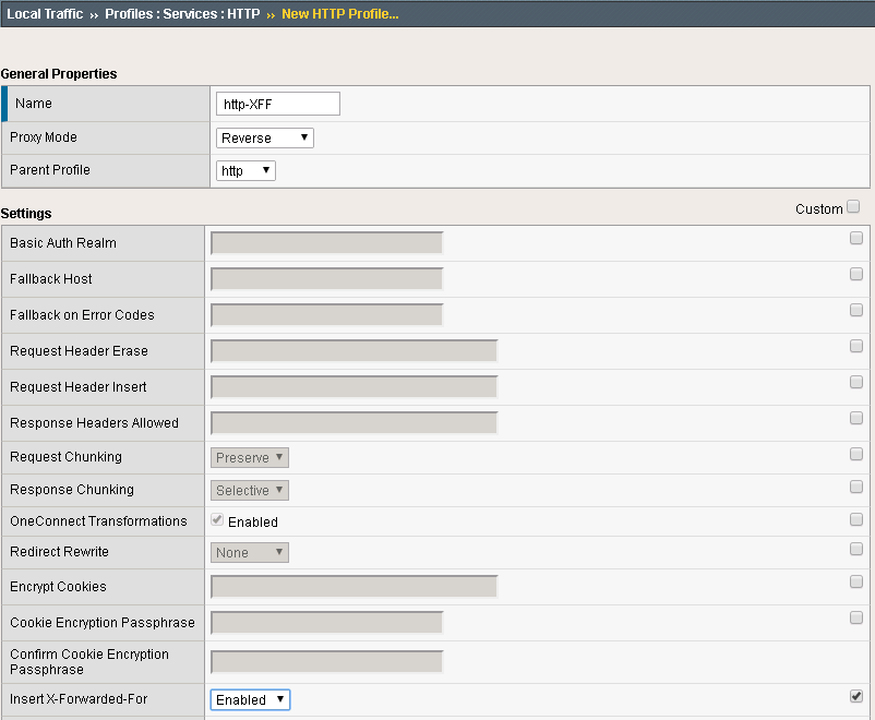
In the Demo LTM is configured to use cookie persistence, insert X-Forwarded-For headers, and use Priority Groups for delivering traffic.
Pools
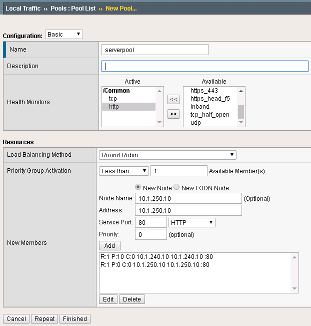
Create a pool “serverpool” on each BIG-IP. Local Traffic -> Pools
Assign HTTP and TCP monitors Enable Priority Group Activation with “1 Available Member”
| Device | Pool Member #1 | Port | Priority Group | Pool Member #2 | Port | Priority Group |
|---|---|---|---|---|---|---|
| bigip1 | 10.1.240.10 | 80 | 10 | 10.1.250.10 | 80 | 0 |
| bigip2 | 10.1.250.10 | 80 | 10 | 10.1.240.10 | 80 | 0 |
Pool config example:
Virtual Servers
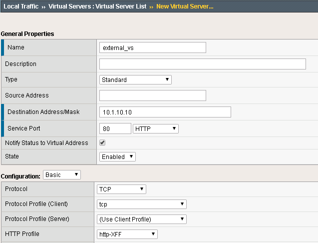
In the next step create two standard TCP virtual servers per BIG-IP. One external and one internal. Apply the http-XFF profile, SNAT Automap and the pool “serverpool”
Use following IP addresses
| Device | Name | Address | Port |
|---|---|---|---|
| bigip1 | external_vs | 10.1.10.10 | 80 |
| bigip1 | internal_vs | 10.1.10.100 | 80 |
| bigip2 | external_vs | 10.1.30.10 | 80 |
| bigip2 | internal_vs | 10.1.30.100 | 80 |
Here a configuration example:


DNS Topology
After BIG-IP DNS and BIG-IP LTM are configured and ready to run, it is time to create the logical geographical load balancing. BIG-IP DNS will receive DNS requests and respond based on the location of the requesting IP.
The demo will show two sections:
- Split DNS: BIG-IP DNS will respond to internal clients with private IP addresses differently than for external clients with IP addresses that are not internal.
- regional Loadbalancing - based on the region of the client IP the response will be different.
- Note: we will simulate the requin with a private IP address range, because this lab is not exposed to the Internet.
The steps to create geolocation based load balancing on BIG-IP DNS are:
- add the virtual servers
- create the pools
- create wide-IPs
- create regions
- create records
All configurations have to be applied one BIG-IP DNS only. The config changes will be synced to the other BIG-IP DNS via a sync group that was created before.
Step 1: Virtual Servers
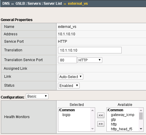
BIG-IP DNS has to be aware of the services that are provided by BIG-IP LTM. BIG-IP DNS sees BIG-IP LTM as a Server that is bound to a datacenter. For BIG-IP DNS the virtual servers on the BIG-IP LTM are virtual servers on the server in the datacenter.
Create the virtual servers on BIG-IP DNS under:
DNS -> GSLB -> Servers
Use following IP addresses for the virtual servers:
| Device | Name | IP:PORT | Health Monitor |
|---|---|---|---|
| bigip1 | external_vs | 10.1.10.10:80 | bigip |
| bigip1 | internal_vs | 10.1.10.100:80 | bigip |
| bigip2 | external_vs | 10.1.30.10:80 | bigip |
| bigip2 | internal_vs | 10.1.30.100:80 | bigip |
Here an example:
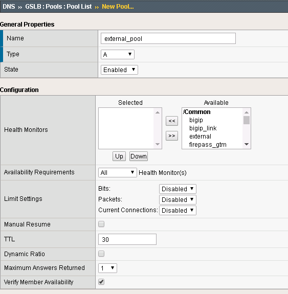
Step 2: Pools
The next step is to configure the pool. under: DNS -> GSLB -> Pools
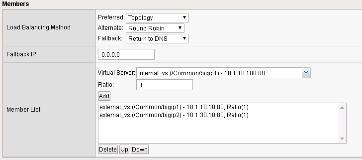
Configure two pools (internal_pool and external_pool) with following load balancing methods: * Preferred: Topology * Alternate: Round-Robin * Fallback: none
use following settings:
| Name | Type | Pool Members |
|---|---|---|
| external_pool | A | bigip1:external_vs, bigip2:external_vs |
| internal_pool | A | bigip1:internal_vs, bigip2:internal_vs |
Here an example:
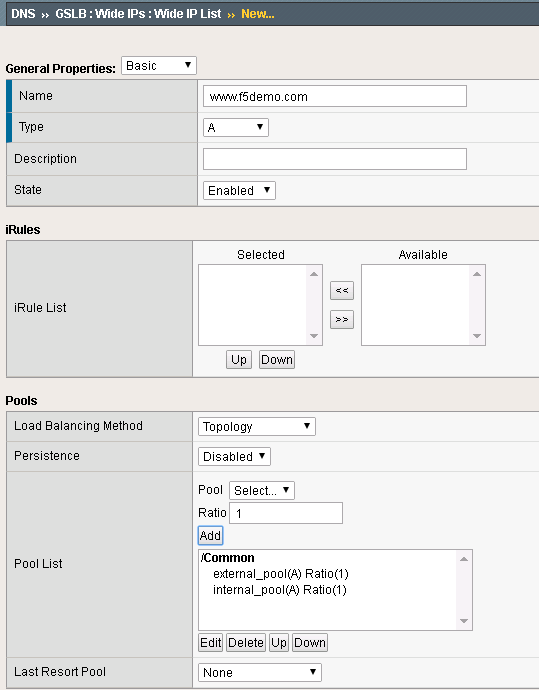
Step 3: Wide IPs
The next step is to configure the Wide IP. under: DNS -> GSLB -> Wide IPs
use following settings and Topology as load balancing method
| Name | Type | Pools | Last Resort pool |
|---|---|---|---|
| www.f5demo.com | A | external_pool, internal_pool | external_pool |
Here an example:
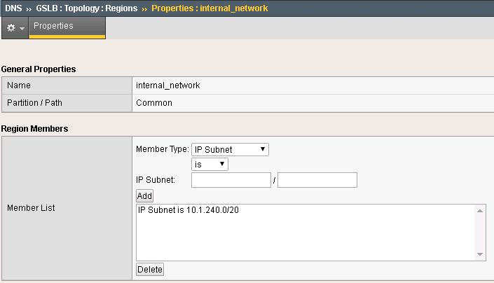
Step 4: Topology Regions
The next step is to define regions that will be used by topology records. under DNS -> GSLB -> Topology -> Regions
Use following IP addresses:
| Name | Subnets |
|---|---|
| internal_network | 10.1.240.0/20 |
| region_1 | 10.1.10.0/24,10.1.240.0/24 |
| region_2 | 10.1.30.0/24,10.1.250.0/24 |
Here an example:
Step 5: Topology Records
The last step is to define the topology records, that BIG-IP DNS will use for load balancing decisions under DNS -> GSLB -> Topology -> Records
use following settings
| Source | is/is not | Destination |
|---|---|---|
| region /Common/internal_network | is not | pool /Common/external_pool |
| region /Common/internal_network | is | pool /Common/internal_pool |
| region /Common/region_1 | is | region /Common/region_1 |
| region /Common/region_2 | is | region /Common/region_2 |
Verifying configuration
Testing Internal Connections
Now it is time to test if your configuration works.
Now run the “Test Server1” link.
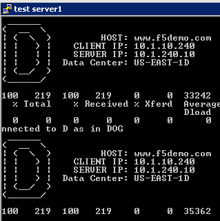
and run the “Test server2” link.
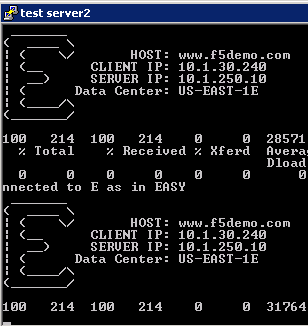
The “test-server[1-2]” links are simulating requests from internal clients. Note that BIG-IP DNS is configured to prefer requests to the same Data Center.
Question Can you explain how this is being done?
Testing External Connections
Find the “Test External” link.

Double-click on it and you should see:
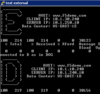
The “Test External” link is simulating requests from an external client. BIG-IP DNS is configured to use round-robin load balancing between the two backend servers.
From Google Chrome find the link for “www.f5demo.com”. The Windows Desktop client is configured to act like an external client.
Question Using Google Chrome the requests will always go back to the same server, why?